
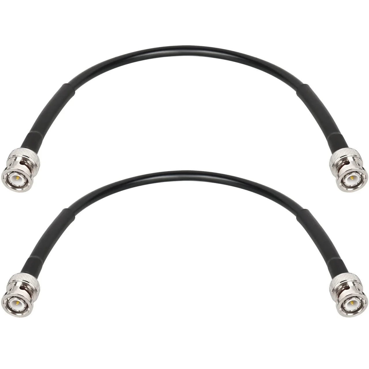
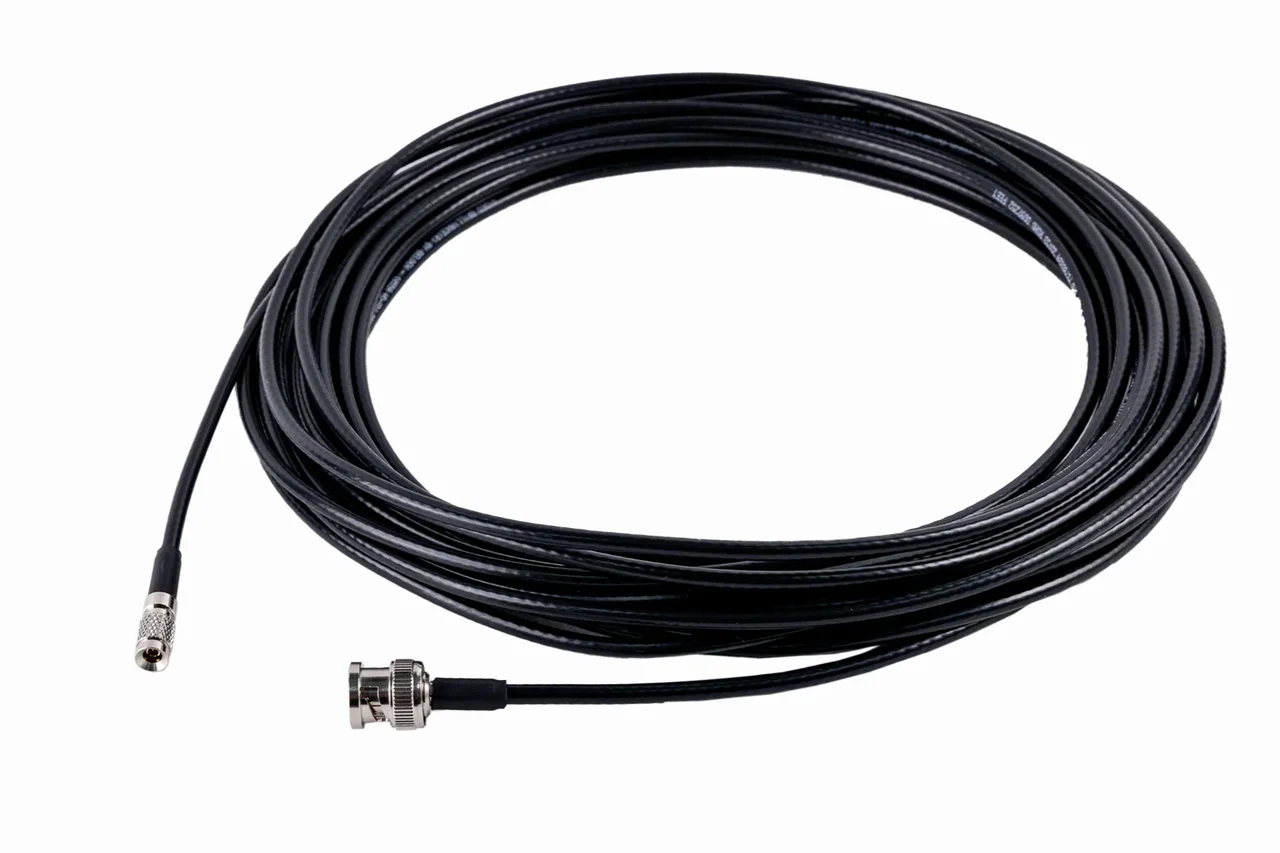
DIN 1.0/2.3 to BNC Cable — CoaXPress
1 / 18
View all product images (18)
- DIN 1.0/2.3 to BNC Cable — CoaXPress — QC13A01 — image 1
- DIN 1.0/2.3 to BNC Cable — CoaXPress — QC13A01 — image 2
- DIN 1.0/2.3 to BNC Cable — CoaXPress — QC13A01 — image 3
- DIN 1.0/2.3 to BNC Cable — CoaXPress — QC13A01 — image 4
- DIN 1.0/2.3 to BNC Cable — CoaXPress — QC13A01 — image 5
- DIN 1.0/2.3 to BNC Cable — CoaXPress — QC13A01 — image 6
- DIN 1.0/2.3 to BNC Cable — CoaXPress — QC13A01 — image 7
- DIN 1.0/2.3 to BNC Cable — CoaXPress — QC13A01 — image 8
- DIN 1.0/2.3 to BNC Cable — CoaXPress — QC13A01 — image 9
- DIN 1.0/2.3 to BNC Cable — CoaXPress — QC13A01 — image 10
- DIN 1.0/2.3 to BNC Cable — CoaXPress — QC13A01 — image 11
- DIN 1.0/2.3 to BNC Cable — CoaXPress — QC13A01 — image 12
- DIN 1.0/2.3 to BNC Cable — CoaXPress — QC13A01 — image 13
- DIN 1.0/2.3 to BNC Cable — CoaXPress — QC13A01 — image 14
- DIN 1.0/2.3 to BNC Cable — CoaXPress — QC13A01 — image 15
- DIN 1.0/2.3 to BNC Cable — CoaXPress — QC13A01 — image 16
- DIN 1.0/2.3 to BNC Cable — CoaXPress — QC13A01 — image 17
- DIN 1.0/2.3 to BNC Cable — CoaXPress — QC13A01 — image 18
QC13A01 — DIN 1.0/2.3 to BNC Cable — CoaXPress. Connector A: DIN 1.0/2.3; Connector B: BNC.
Review the connections and installation requirements for this assembly. Share the model and your project requirements for a quotation.
- Connector A
- DIN 1.0/2.3
- Connector B
- BNC
- Interface
- CoaXPress
- Cable length
- 3 m / 5 m / 10 m / 15 m
Confirm the exact configuration, dimensions and application requirements before ordering.
Technical overview
- Model
- QC13A01
- Construction options
- 23AWG / 24AWG
- Installation options
- Fixed installation / continuous-flex variant; validate bend radius, travel and cycles for the selected configuration.
- Product family
- Machine vision
- Connector A
- DIN 1.0/2.3
- Connector B
- BNC
- Interface
- CoaXPress
- Listed length options
- 3 m / 5 m / 10 m / 15 m
Details that make the difference.
Confirm both equipment interfaces and pinouts.
Check mounting dimensions, orientation and available space.
Specify length, installation environment and movement.
Agree the drawing revision, sample and inspection requirements.
QC13A01
Check before ordering
A matching connector alone does not confirm the required data rate or suitability for movement. Share the camera model, cable length and routing conditions for review.
Request a drawing ↗Start with your equipment
Start with the camera and frame grabber interfaces. Compare the connector at each end, screw-lock position and exit direction against the available installation space.
- Connector A
- DIN 1.0/2.3
- Connector B
- BNC
Compare recorded configurations
Confirm the exact configuration, dimensions and application requirements before ordering.
| Model | Connector A | Connector B | Interface | Listed length options |
|---|---|---|---|---|
| QC13A01 | DIN 1.0/2.3 | BNC | CoaXPress | 3 m / 5 m / 10 m / 15 m |
| QC13A00 | BNC | BNC | CoaXPress | 3 m / 5 m / 10 m / 15 m |
| QC13A02 | DIN 1.0/2.3 | HD-BNC | CoaXPress | 3 m / 5 m / 10 m / 15 m |
| QC13A03 | DIN 1.0/2.3 | DIN 1.0/2.3 | CoaXPress | 3 m / 5 m / 10 m / 15 m |
Selection guides and project support
Related assemblies
Compare the connector combinations before choosing a model.
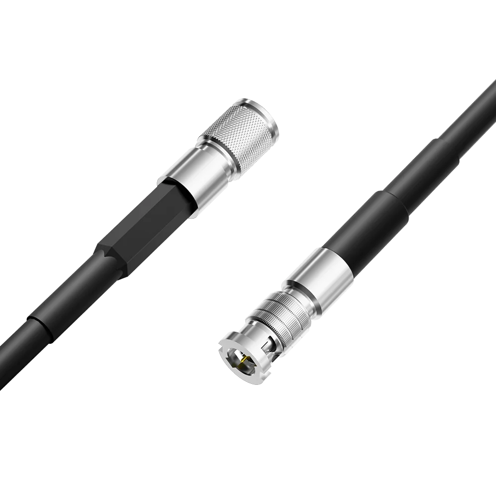
QC13A02
DIN 1.0/2.3 to HD-BNC Cable — CoaXPress
DIN 1.0/2.3HD-BNC
View cableListed length options: 3 m / 5 m / 10 m / 15 m
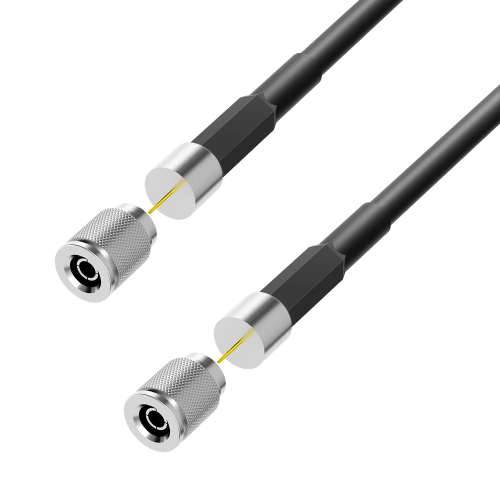
QC13A03
DIN 1.0/2.3 to DIN 1.0/2.3 Cable — CoaXPress
DIN 1.0/2.3DIN 1.0/2.3
View cableListed length options: 3 m / 5 m / 10 m / 15 m
QC13A01
Request a quote
A model number, connector pair or drawing is a useful place to start.
Details that make the difference.
Confirm both equipment interfaces and pinouts.
Check mounting dimensions, orientation and available space.
Specify length, installation environment and movement.
Agree the drawing revision, sample and inspection requirements.
Request a quote…
Email: sales@qicable.com